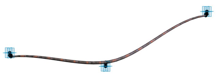
 A few days ago I received some thoughts from Ben Osborne at McVeigh & Mangum Engineering in Atlanta on modeling post tension structures in Revit. Or, more precisely, the post-tension reinforcing bars. We had some discussions back and forth around Adaptive Components (AC’s) and Flex Pipes, and I decided to pursue the AC solution.
First, a couple of pre-requirements. The bars need to be able to shift between variable number of “ups and downs”. Because Adaptive Components have a fixed set of Adaptive Points, that means one family for each set of these.
I also need to be able to control tangent angel for each point. This seems difficult as I can find no other way of doing so than adding additional Reference Points very close to the geometry points. I’m sure the angle these form with the geometry points can be parameterized somehow, but in this example I’ve settled for horizontal tangents.
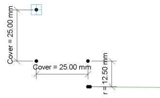
Last, the geometry of the bars should never exceed the concrete cover, meaning the “ups” and the “downs” needs to be offset by one radius from the original Adaptive Point.
Based on the Adaptive Point I add new Reference Points, hosted as a chain so that if I move the Adaptive Point all the other (4 in the example above) move with it.
The distances between the points are length parameters associated with the Offset parameter of the Reference Points. In order to make this work both ways (the different high and low extremes have both positive and negative offset values) you want to set up inverted duplicates of all length parameters.
When all points are in place I host the nice face-based anchor family that Ben has produced to the end points, and voila; Fully parametric post tension bar, flexible in all imaginable directions and pretty easy to model.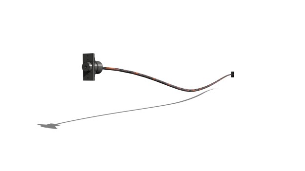
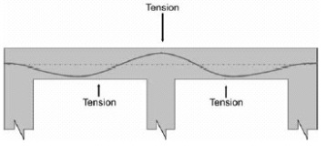


Pingback: Post Tension Structures in Revit | Håvard Vasshaug – Yet Another BIM Blog
Pingback: Post Tension Structures in Revit – Yet Another BIM Blog
In one of the comments you talk about coping the middle point around to create as many points as needed and then rehosting them… Do we just copy the point with the number or all the points associated with that number. For instance point 4 has 1 point with a number and three more in the element. Could you please walk me through how to rehost the point and which points to copy. I am not seeing a way to rehost the points either. I am trying to make a PT cable with 7+ points.
Hi Havard!
Many thanx for your examples. I’ve made an 11-point pt-family, based upon your’s. I have made nice anchor heads also (Dywidag 6819). Every works fine; execpt for one element. When I place mine version of the family in a cut section on a workplane, and the spline reference line in the center is atached to the workplane, something funny happens. When I look from above, the spline reference line from the family is indeed exactly in the right workplane. The tube around the spline reference line however is not. It jiggels around the straight reference line. Same thing happens when I try you’re original family. Is there a parameter of a way of inserting that’s going wrong? Any idea’s?
Again: thanx for you’re example! But if you know any tips on my question, i would be very thankfull.
And not a long time after I found out why the tube isn’t lining up with the reference spline. When you insert the family into a project, one gets a set of grip points. These grippoints are the adaptive points. In the family the adaptive points are slightly above or below the reference spline, what causes the family to go slightly of the workplane in the projectfile while the reference spline stays on the workplane: the adaptive points introduces a sort of an offset. Nothing to hard te fix.
ps: this reply is not meant to brag or something else; without this blog I would not be able to make a pt-family at all. 🙂
I have to apologize a bit; there’s nothing wrong with you’re pt-family What I did wrong: while I was constantly working in a side-view editing the pt-family to host more points, I got used to the view. Back in the main model I tried to host the pt-family into the same view. Thus I tried to host it to the side of my bridge, instead of to the bottem side of the deck. If you insert the family by workplane and set up a reference-plane at the bottem of the deck of the bridge, everything goes perfect.
I’m very glad to hear that Ron! I’m impressed that you figured it out:)
I have been working on slightly alternative methods for modeling PT the past months, and plan on writing a blog post about it shortly. You can read about it in the PT section of my RTCNA handout material at https://vasshaug.net/2013/08/30/revit-technology-conference-north-america-2013/
The background for me wanting different methods is I wanted to make a family with only two placement points, so that the entire tendon would always be aligned. I don’t know yet how successful this exercise will be, but I think it’s worth the try.
Thank you for your feedback and opinions!
Thanx for you’re reply. Within a pt-family, I can not rotate grip points. Thus a tendon in my family can not be bended to the exact requirements we need. I’ve solved this by inserting the family into the main model. When one makes a cut-section on the same place as the tendon, one can adjust the grip points in the view of the cut-section. In this way, the grip points can be rotated and the tendon get’s precisely the flowing curbes it’s needed. 🙂
Sure: http://www.gratisimage.dk/image-F82E_518200F5.jpg
I’m very interested in an easy way to make annotation on the placement of the tendons. Perhaps a macro is the way to go?
I’m not sure exactly how that would be built, but you can model a void family and cut out the opening outlines from the PT’s in question. That will obviously not automatically produce new anchors – you’d have to model those additions manually.
Regarding annotation, you can use Spot Elevation on the Reference Points in the project environment. As long as you annotate the high’s and low’s I think you’re in the clear.
Hi Håvard,
Very interesting subject with PTE modelling.
Du you have any pointers, on how to handle PTE modelling around slab openings?.
My experience with PT modeling is limited to these Adaptive Component tests unfortunately. But if you could provide an illustration..?
Hi Max,
The download content doesn’t seem to work. I am working on a project where we need to model all the PT anchors so I wanted to use what you created already.
Also, I had a question about model size, a couple years ago I worked on a project where we modeled the PT tendons and the revit file quickly went from 70MB to 500MB just by adding about 20 tendons. I used a generic model in place using a sweep along a spline, I’m sure this isn’t the most efficient way, but it was the quickest way I knew at the time.
Cheers.
I’ve updated the link to point to my content section. It should work now. Thanks for letting me know.
Please feel free to use whatever you need, but be aware the families still need some tweaking. I’m no post tension expert and still receive feedback on how these can work even better.
I do not see any big impact on file size while using Adaptive Components.
Revit do not have a PT tendons family OTB in the structural framing template.
Yes, you are right! But we can create it
Hi, Håvard. PT rebars modeling via adaptive components is a good idea. But for this purpose I usually use PT tendons family based on structural framing template . It not only creates the tendons, but also sends an analytical model with all loads from post tension in RSA for further analysis. You can read more on my blog: Perfect Project
Yes, I can see how that can be useful Max. However, I love the way I can control the curves with points, and also the possibilities opened by surface, patterns and path hosting.
And being able to use the Repeater feature in 2013.
Max, the link to your blog says the page does not exist! Interested in how you are using structural framing template with PT and RSA. Are you revising the page?
Hi, Steve! You can read this: http://goo.gl/bRl8Q Also on YouTube: http://youtu.be/i5mnLPIdXwE
How would you add those extra “ups and downs”? Could you upload another version of your family with a couple more “ups and downs”?
Thanks
Yea, it’s pretty easy. You just copy the middle point around, and rehost the new reference points (some lose their host references when they are copied). Then you produce a new reference spline by points and redo the circle and sweep. I’ve uploaded a new file with 5 points – 3 ups and 2 downs. It’s in the Content section.
Thanks, Håvard
Hi, Håvard. I’m having some trouble making a 7 and 9 point tendon. Could you upload it our give me a step by step demonstration on how to make it. much appreciated.
Hi Ragnar Thor. I’m sorry for the late reply. I’ve been working on alternative modeling techniques the past months and didn’t want to post anything before it was finished. And as always, it never is. Please expect a blog post in the near future about these methods, and also check out the section about post tension tendons in my published rebar handout material from this year’s RTCNA at https://vasshaug.net/2013/08/30/revit-technology-conference-north-america-2013/
In theory, making 7- 9 or 18-point tendons should be fairly simple. Just a repetition of the procedures with making a 3-point family. Could you elaborate the trouble you are encountering?